Monday, May 3, 2010

Diagrams 1.0


01 a. Symbol overlay
b. Road Access
c. Sun Study
d.Train Access


02 a. Expansion of symbol
b. frustration at a
c. -
d.-
I realized i was going to fast and needed to get back to basics

03 a. Diagram 01 - Thinking about arrival sequence
b. Diagram 02 - Thinking about arrival sequence
c. Diagram 03 - Still thinking about arrival sequence
d.Diagram 04 - Thinking about spaces that create desired arrival sequence
04 a. Diagram 05 - Thinking about spatial requirements/optimal location
b. Diagram 06 - Thinking about connection
c. Diagram 07 - Still thinking about connection
d.Diagram 08 - Identifying spatial types that create desired arrival sequence

many more to come (they are stuck in my design diary)

Site


During my pitch i identified two possible sites for my stadium and surrounding uses, below is a quick analysis of each in order to confirm a final site.

Site 01


This location is highly accessible by three large infrastructure systems, The new gateway, the existing main road and the proposed rail system. Unfortunately the site may fall under the future runway project if it is constructed.

This site has the ability to make many positive connections to its surrounding uses. It can connect to infrastructure, parks, proposed hotels, the airport (though new rail) and the DFO. Furthermore it contains enough separation from each of these uses so as not to negatively impact on their respective functions. ie as it is not to close to the airport it will not produce congestion.


Site 02
This location has the ability to connect to the three infrastructure systems, however its connecting to each is not as strong as the previous site. This site also may fall under the future runway project if it is constructed.

This site has fewer connections to other surrounding uses that may increase the success of the proposed uses. Its proximity to neighboring uses such as the DFO may have a negative impact on its existing function.


Plane Heights
It was identified that each site may fall under a future flight path. This would have a major influence on the design of the stadium as the planes would distract from events within the space. To completely understand the impact of planes on each site i investigated landing and take off abilities and regulations of current airplanes. Through my investigation it was noted that the landing of the planes will have the greatest effect as they require a smaller approach angel or glide angle. Below is a diagram of the acceptable and possible glide angles of a Boeing 747.


My research identified that a Boeing 747 can land at an incline between 2 and 15 degrees however the average glide angle used within the commercial arena is 4 degrees. Between 10 and 15 degrees is acceptable by commercial airlines however is only used in rare cases. It was noted that flight paths can easily be changed to suite weather conditions, noise restrictions, buildings and events. Thus i am proposing that during events a glide angle between 6 and 8 degrees is adopted to reduce noise, shadows and visual distraction during open air events. This would then negate the impact that planes have on both sites one and two


Conclusions

After this very quick analysis of the key influential factors i have chosen site one as the site in which to construct the stadium and surrounding uses. Their is obviously many other factors that effect each site however most would be very similar due to proximity of each, and would therefor not change my conclusion.

Sunday, April 18, 2010

Design Brief


You must provide a space for the mass gathering of a community to view and participate within a multitude of differing events. The space is to embody the notion of social gathering and manifest within a structure that represents the community’s pride and portrays its aspirations. The space must explore ideas of multi-function to create a place of vibrancy during non-event times. This idea of multi-function is not to be contained within the viewing space, but it is to be embraced to all uses across the site in an attempt to maximise social interaction. With this in mind the space must integrate into the surrounding context and take advantage of any existing assets. You must also explore the idea of the crowd in order to identify and deal with issues of circulation, safety, service requirements and the desired spatial experience. Finally as the main function of the space will involve mass movement of people the space is to embody and explore notions of mass multi model transit systems and ideas of sequence in order to heighten the users experience upon arrival.

Curve Generation - Model 01

I decided to make a model that was generated by the flight path of a football as this would be one of the key movements that would occur within my building.

">


To create my curve I had to determine three variables, the initial point and velocity of the ball (a), the height of the ball (b) and the distance of the ball (c).


The distance would be determined by the initial and final ball velocity and the negative acceleration caused by friction and gravity. I can use the function

v2 = u2 +2as
where
v=final velocity
u= initial velocity
a= gravity (its horizontal influence so not 9.8m/s2 ) and friction
s= distance

therefore I must transpose for s
s= v2-u2 /(2a)

To make things easy I made the ball stationary (0m/s) therefore its initial velocity would be the same as the foot that is kicking it. (loss of force durance transition from foot to ball is relatively negligible as the bounce/spring of the ball makes up for its lighter mass than the foot). I made the initial velocity to be between 0m/s and 9.5m/s after reviewing collated data/google ;) . Final velocity will equal 0 as this is when the ball has stopped (i am not calculating it bouncing on, that's too hard). Finally the acceleration was determined again by research to be about -.7m/s

So
v=0
u= 0 to 9.5
a= -.7
s= distance


The height of the curve is determined by the angle at which the foot hits the ball. Simple the height equals the tan of the angle multiplied by the distance. The angle of the foot striking the ball can range from 0 to 90 degrees.


The curve of the ball is determined similar to the height. The only difference is as the ball is struck further to the side it cannot curl back to its original y axis. I determined this as being 1/4 of the distance of the apex of the curl. This is shown in the f(x) function in grasshopper.


To then use this information to create a form i decided to plot three curves and loft through them. The result is below.


Unfortunately when i exported this to Corel i had scale issues and to be able to cut the peices large enough i had to scale them up in the x and y plan but i could not do that ion the z plan. This is the reason that the model is short and stumpy.


I also cut the same pieces at a larger scale again and put them together in a differing form. Below is the result. I think that in some ways this model is more of a success than the original. It starts to explore this idea of stepping that i would like to pursue and develop for my project.


Rhino & Grasshopper Beginnings

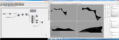
This is my first go at rhino and grasshopper. I think at the moment i can follow the basic steps and make some nice forms, but ill have to develop my understanding of the tools and functions before i can create something intentionally. I took the opportunity to explore software compatibility and export pathways with aim of being able to document the structure in the final stages. For those interested here are the steps to get to archicad.


1. Export .stl file from rhino.

2. Import .stl file into cinema 4d. Cinema 4d is very similar to 3ds max but works simultaneously with archicad. It does this by creating an object out of your original stl file, and locating it within the archicad library. Then if you make any changes it automatically updates.

3.Save as a cinema 4d file


4. Open the cinema 4d file in archicad.

5. Place the object in the desired location in the model space. Now you can document your form (in my case a wall) Ive created an elevation of my wall that i can now dimension if i want. The best bit is that archicad will actual cut the object at sill hight in the floor plan view. So you get a real arcutare floor plan of your form.