I decided to make a model that was generated by the flight path of a football as this would be one of the key movements that would occur within my building.
To create my curve I had to determine three variables, the initial point and velocity of the ball (a), the height of the ball (b) and the distance of the ball (c).

The distance would be determined by the initial and final ball velocity and the negative acceleration caused by friction and gravity. I can use the function
v2 = u2 +2as
where
v=final velocity
u= initial velocity
a= gravity (its horizontal influence so not 9.8m/s2 ) and friction
s= distance
therefore I must transpose for s
s= v2-u2 /(2a)
To make things easy I made the ball stationary (0m/s) therefore its initial velocity would be the same as the foot that is kicking it. (loss of force durance transition from foot to ball is relatively negligible as the bounce/spring of the ball makes up for its lighter mass than the foot). I made the initial velocity to be between 0m/s and 9.5m/s after reviewing collated data/google ;) . Final velocity will equal 0 as this is when the ball has stopped (i am not calculating it bouncing on, that's too hard). Finally the acceleration was determined again by research to be about -.7m/s
So
v=0
u= 0 to 9.5
a= -.7
s= distance

The height of the curve is determined by the angle at which the foot hits the ball. Simple the height equals the tan of the angle multiplied by the distance. The angle of the foot striking the ball can range from 0 to 90 degrees.

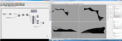
The curve of the ball is determined similar to the height. The only difference is as the ball is struck further to the side it cannot curl back to its original y axis. I determined this as being 1/4 of the distance of the apex of the curl. This is shown in the f(x) function in grasshopper.

To then use this information to create a form i decided to plot three curves and loft through them. The result is below.

Unfortunately when i exported this to Corel i had scale issues and to be able to cut the peices large enough i had to scale them up in the x and y plan but i could not do that ion the z plan. This is the reason that the model is short and stumpy.


I also cut the same pieces at a larger scale again and put them together in a differing form. Below is the result. I think that in some ways this model is more of a success than the original. It starts to explore this idea of stepping that i would like to pursue and develop for my project.


